Unit 19: Class Diagram
Learning Objectives
After this unit, students should be able to:
- use class diagram to design classess/interfaces and the relationships between them;
- translate class diagrams into code;
- design and reason about solutions using class diagram.
Overview
In the previous units, we used inheritance, overriding, and overloading to design our class hierarchy. Our fields/methods may also be annotated with different modifiers. We also introduced different kinds of abstract types such as abstract class and interface.
In this unit, we introduce class diagram to visualize and understand relationships between classes/interfaces at a glace. This helps spot issues before they occur. Additionally, this allows us to communicate our design more effectively to other people.
Class Diagram
Class diagram is a way to model our classes/interfaces without coding them. It is part of the Unified Modeling Language (UML), but will not use the full feature of UML. Our brief introduction to class diagram covers only parts that are useful for our course.
Class
A class diagram records only the summary of a class. The simplest element of a class diagram is a class. It is drawn as a rectangle divided into three sections.
- Class Name.
- Fields.
- Methods.
In between each segment we draw a line to clearly delimit each segment. For best result, the order in which the fields and methods appear should be identical to how they appear in the code.
In essence, this is a summary of class. We can summarize class fields with their names and types. This is applicable for both instance field and class fields. Unlike method descriptor, our summary of a method adds the parameter names back to avoid potential confusion with the role played by the parameter.
Access modifiers are represented as follows.
| Modifiers | Symbol |
|---|---|
private |
- |
public |
+ |
Consider the simple Circle v0.7a reproduced below. Note that constructor has no return type, so it will be omitted in the class diagram.
| Circle v0.7a with Overriding equals | |
|---|---|
1 2 3 4 5 6 7 8 9 10 11 12 13 14 15 16 17 18 19 20 21 22 23 24 25 26 27 28 29 30 31 32 33 34 35 36 37 38 39 40 41 42 43 44 45 46 47 48 49 50 | |
The class diagram is as follows.
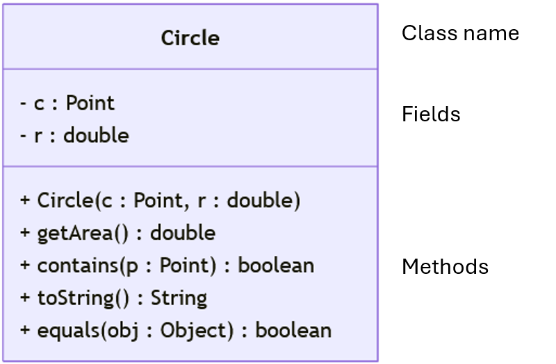
Consider the contains(Point) method.
1 2 3 4 | |
The required summary for class diagram is simply public boolean contains(Point p). Converting this to the notation for class diagram, we get + contains(p : Point) : boolean.
Be Explicit
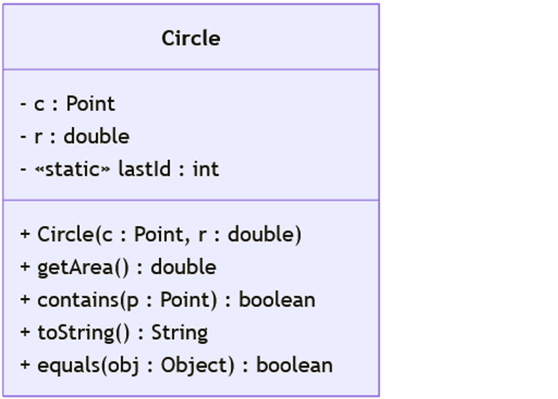
Unlike the proper UML class diagram, we will simply ask you to be explicit when drawing your class diagram. If you require a field to be static, then add «static» to the field. If you require a method to be abstract, then simply add «abstract». The symbol « .. » can be used for any modifiers needed in this course.
Relationships
We can represent inheritance using arrows. This is the same idea as we have seen for primitive subtyping. There are two kinds of arrows for two different kinds of inheritance. If we inherit from a class, then we use solid arrows. If we inherit from an interface, then we use dashed arrows.
Consider the following classes/interfaces and their relationships.
| Surface, Shape, and Circle | |
|---|---|
1 2 3 4 5 6 7 8 9 10 11 | |
We can represent them in a class diagram as follows.
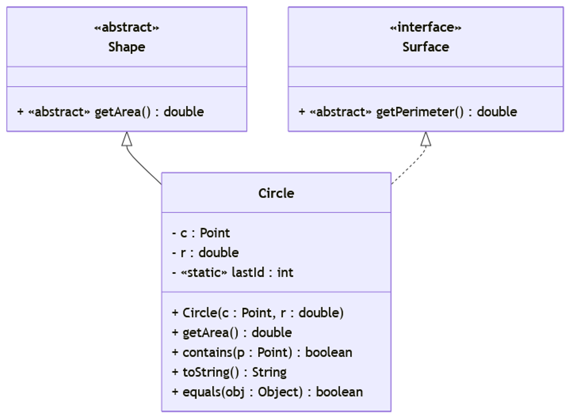
The class diagram above allows us to also find issues with our current design. In particular, notice that the class Circle has no non-abstract method that overrides public double getPerimeter(). Additionally, the class Circle itself is not declared abstract. As such, this design will produce compilation error before we implement the class.